6. Range Generation
6.1. Concept
Range generation is a generation mode primarily intended for multi-segment monochrome (e.g. CT) datasets, although it can also be used on colour datasets. In range generation the user splits up the range of possible greyscale values (from black to white) in the source image into sections corresponding to different types of material, and assigns segments to each. Figure 12 shows an example of one such dataset, where a fossil is preserved as both void (dark) and pyrite (white), and two segments are defined using the range system to cover the darker pixels (‘Default’) and the lighter ones (‘Segment 2’).
To implement range-based generation, the user first creates the required number of segments (see above). With the Generation panel in Range mode (the Range tab selected), the positions of the segments in the black-white gradient can be set using the controls detailed below; in practice it is normally best to start with a Distribute Over Range command to ‘separate’ the segments, which by default will be overlapping and not arranged in any sensible way. In the same way that linear generation for single-segment datasets is normally initiated by finding optimal values on a single ‘test’ slice, range generation is also best set up in this way, using the Auto tick box to apply changes as they are made until optimum settings have been determined, and the Range generation can be applied to the same dataset. Note that segment boundaries are allowed to overlap, but this is rarely a sensible thing to do, and should be avoided unless the user is confident they know what they are doing!
Range Generation (i.e. clicking Generate or using Auto and making changes) affects all selected slices as does normal generation, but unlike generation in Linear or Polynomial modes it also affects ALL segments, not just the selected one.
6.2. Range Generation Panel
The Generation Panel in range mode consists of a shaded strip running from black to white (representing the range of shades to be assigned), together with Base and Top ‘spinboxes’ and two tick boxes. Segments are shown on the strip occupying the range currently assigned to them; the currently selected segment (the one in the ‘L’ drop-down of the Main Toolbox panel) is shown in a lighter colour, with a green border, and the Base and Top values shown apply to this segment, representing the range on a scale covered where 0=black, 255=white.
Selecting Segments: Left-clicking on the coloured block representing the segment on the shaded strip will select it (i.e. have the same effect as selecting it in the L dropdown on the Main Toolbox panel).
Dragging boundaries. Using the either mouse button you can pick up and drag the left and right margins of segment blocks in the shaded strip to reposition them (i.e. change the Base and Top values of the segments). If you use the left mouse button, margins will ‘snap’ onto adjacent margins to ensure no gap in between, and if you drag a margin already in contact with another, both will move together. If you use the right mouse button instead, this ‘intelligent’ snapping and combined dragging behaviour is disabled.
Using Base and Top: With a segment selected, Base and Top values can be altered directly using the spinboxes; no snapping behaviour is implemented.
Selected only: With this box ticked generation affects only the selected segment, not all segments. This option is not normally helpful, and is included only for completeness.
Hard fill: Generates in hard rather than soft-fill mode – see below.
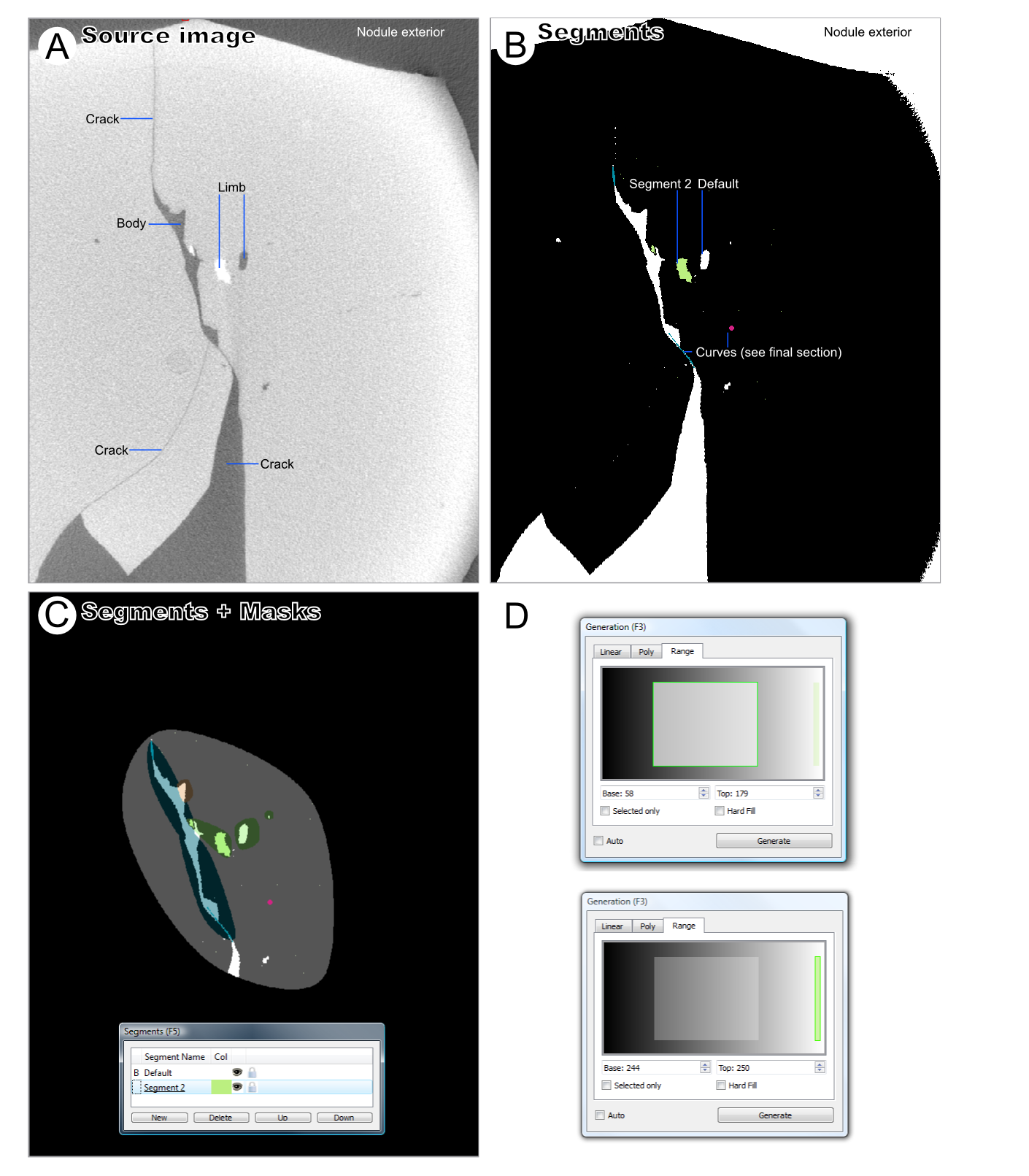
Figure 12. Multi-segment CT dataset handled using range generation.* A; Source Image. B; Thresholded image showing multi-segment interpretation. C; Segmented image with masks overlayed; D, Range generation settings used, top shows ‘Default’ segment selected, bottom shows ‘Segment 2’ selected.
Distributing segments. The Distribute over range command takes all segments selected in the Segments panel and distributes them evenly over a specified range (by default the entire range, 0 to 255). This is primarily useful when setting segments up initially, as a prelude to moving their boundaries to optimal positions.
6.3. Hard and Soft Fills
By default, Range generation uses a ‘soft fill’ algorithm to generate each working image (recall that there is one working image per segment). If source image pixels are at the midpoint of the range, the corresponding working image pixels are fully white. As source image pixel values move away from this midpoint, the corresponding generated pixels get darker linearly, crossing the threshold value (of 127) at the correct points (the specified Top and Base values for the segment), and tailing away to 0 beyond that. Figure 13 provides a visual explanation of soft-fill values for a hypothetical four-segment dataset
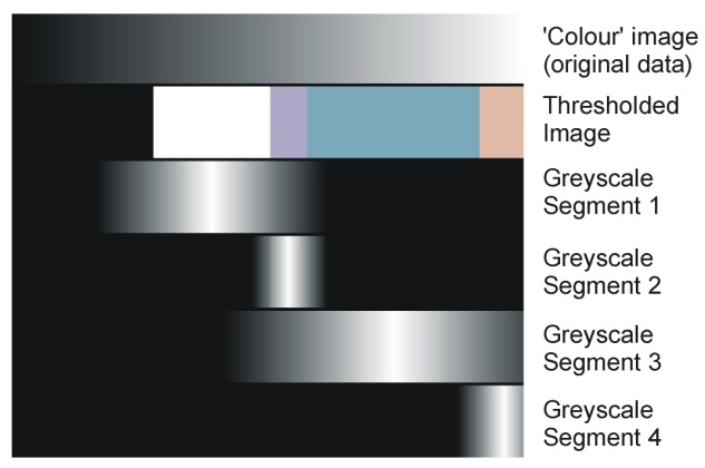
Figure 13. Soft-fill range generation. Top; the grayscale range of the source images. Second row; Segment definitions for four segments. Bottom four rows; working image levels generated for each segment for each source image level.
The point of soft-fill range generation is to enable the brighten brush to be on range-generated dataset. If used on working images generated in this way, it will function to ‘bring out’ a segment, pushing boundaries locally up and down. This allows subtle post-editing after generation.
When generating a single segment, however, soft-fill is not always appropriate; pixels within the specified range might not display as the expected segment if another segment has been artificially brightened at that point. To ensure that all pixels in the designated range are assigned correctly, tick the ‘hard fill’ box. With hard-fill in operation, SPIERSedit sets all pixels in the designated range to pure white in the segment greyscale file, and all outside it to pure black, ensuring that this problem does not arise.