4. Masks
4.1. Concepts
The SPIERSedit mask system allows the user to colour-code different parts of the model. The two most common reasons to do this are:
Defining a region of interest. While it is possible to manually delete all undesired pixels in the background/matrix in each slice, the mask system provides a quicker way to separate off the part of the image with ‘object’ in it from the rest. In Figure 7, a ‘fossil’ mask (light brown) has been used to indicate the region of interest prior to any editing work. The remaining background (still in the black/white colour of the default mask) can then be hidden and excluded from visualisation with a few clicks. A similar approach can be used to identify unwanted structures such as cracks, and exclude them from visualisation.
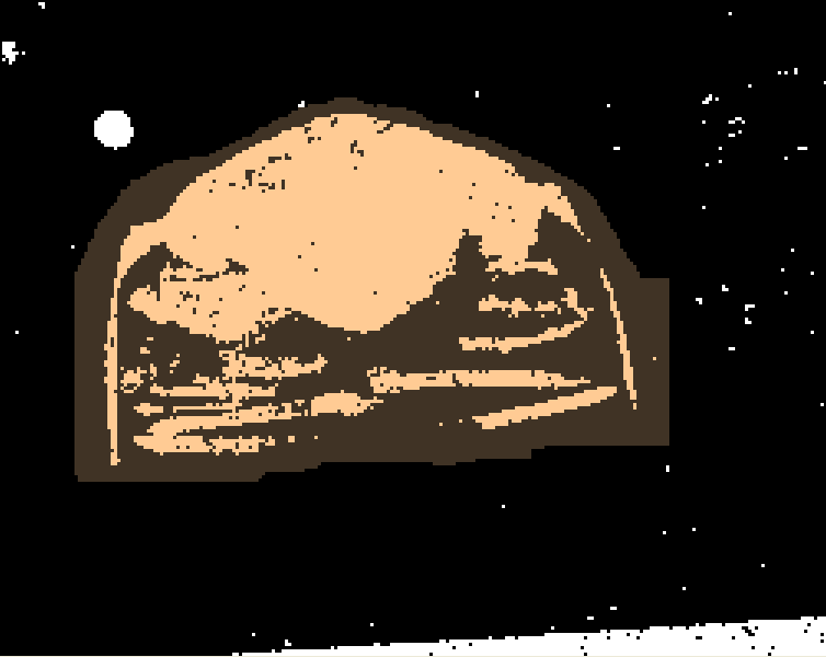
Figure 7. Mask as region of interest.
Splitting a model into sub-units: The most important application for masks is to split the model into several separately coloured units (e.g. split an arthropod fossil into carapace, appendages and trunk). This enables colour-coding for clarity in the final three-dimensional model, and also allows the user to perform ‘virtual dissections’ by interactively hiding/unhiding these units in SPIERSview. In Figure 8, a ‘body’ mask (light brown) has been applied prior to editing (as above), and the background mask hidden from view. After editing, further masks were applied to reassign some parts of ‘body’ to other structures - a carapace mask (blue), and three different appendage masks (purple, red and green) are visible.
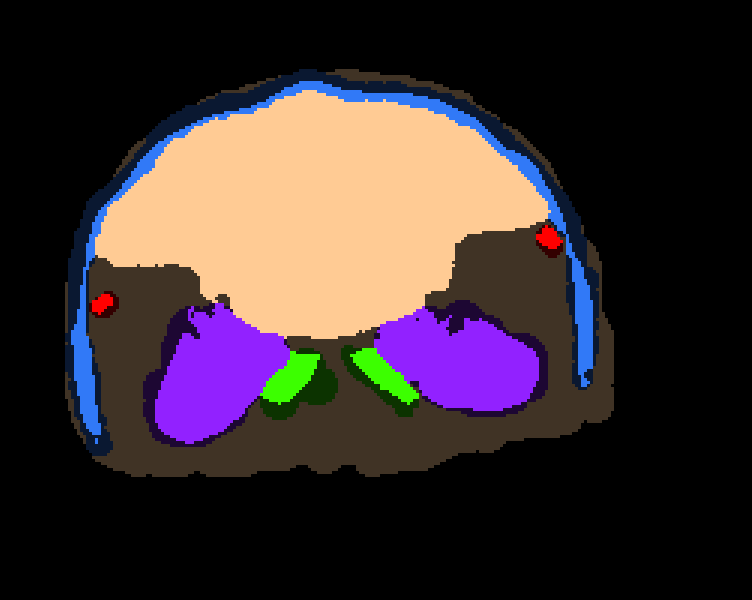
Figure 8. Masks used to identify structures.
Masks are only visible in Mask mode; however, if the Always Show Masks option in the Mode menu is turned on, you will see masks (in a washed-out form) in all other modes (except Lock/selection).
Note that masking affects both ‘on’ and ‘off’ pixels – a light version of the colour is used for ‘on’, and a dark one for ‘off’. Only the ‘on’ pixels will appear in the final model of course, but the colour-coding of ‘off’ regions is there to remind you of the mask that pixels subsequently turned on here will be assigned to. Note that the mask-boundaries in empty regions of the examples above are rough and ready - this doesn’t matter, as there are no ‘on’ pixels here to appear in any reconstruction. Those in ‘on’ regions (such as the inside of the carapace, above) will be rendered as object boundaries, so more care is required.
Colour: Mask colour only affects the colour masks appear in SPIERSedit; while this colour is also used to provide a default colour for output objects when they are created, these can be set independently, and there is no requirement for SPIERSedit mask colours to be those used for objects in SPIERSview; mask colours instead should be chosen so that the user can easily distinguish masks which abut each other when editing. Dark ‘on’ colours should normally be avoided.
Visibility: Masks can be visible or hidden. Hidden masks are still visible in the threshold image as their ‘off’ colour, but no ‘on’ pixels are shown. This only affects viewing of images in SPIERSedit; hidden masks behave just like visible ones for export to SPIERSview. Hiding masks only affects program behaviour if the Hidden masks locked for generation option in the Masks menu is ticked; as expected this option restricts all generation actions performed from the Generate panel to visible masks. This allows different generation rules to be applied for different regions of interest – often useful if there are preservational differences between different structures. Note that the recalc mode brush still affects hidden masks even with this option ticked.
Locking: Masks can be locked or unlocked. A locked mask cannot be overwritten by another mask, either with the mask brush, mask copy commands, or through mask from curve operations (see below). There are many uses for this facility, the most important being the locking of a ‘completed’ mask to avoid accidental changes to it.
4.2. Applying masks
Masks are applied by using the brush in Mask mode. The left and right mouse buttons can be set to apply different masks; these are chosen from the L and R mask dropdowns in the Main Toolbox panel, or alternatively by left or right clicking in the left-hand column of the Masks panel. In this column the R indicates the right mouse button mask and the L indicates the left mouse button mask; if these coincide a ‘B’ (for both) is displayed. Note additionally that selecting a mask in the Masks panel automatically chooses it as the left-mouse mask.
Masks can also be applied using the Masks from Curves and Copy commands (see below); these provide mechanisms for rapidly masking large numbers of slices.
4.3. Advice on use of masks
Masking procedure: When masking a dataset it is normally best to begin masking an isolated part, such as a limb. Find such a structure, and adjust the brush size, create and select a mask, and apply it using the brush to create a coloured zone around a structure to encompass all its boundaries (see Fig. 9). Moving forward or backward through the dataset a slice at a time (most conveniently using the shortcut keys for movement) allows this process to be repeated and structures followed throughout the dataset. It is normally easier to create one mask at a time and apply it to all required slices, rather than create all masks at once and apply them all, slice by slice.
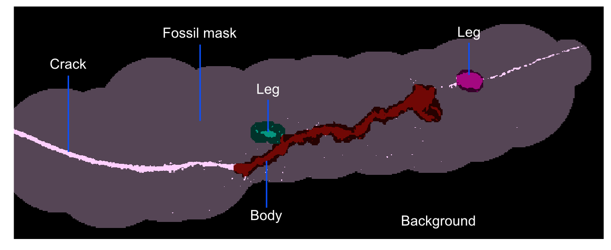
Figure 9. Masking example.
Here a rough ‘Fossil’ mask has been used to pick out a region of interest, facilitating initial inspection of data and removing much of the background (hidden). Three subsequent masks (two legs and a body) have subsequently been more carefully added; at this point only the crack and noise are left in the ‘Fossil’ mask.
Multiple masks: Multiple masks can be easily fused into a single object at output, so there is little harm in using multiple masks for a single structure. This often provides flexibility – for instance part of a structure can be masked separately so that in one version of the output it can be hidden to allow users to see inside an object; in another version of the output it can be fused seamlessly with the rest of the object. As another example ‘left’ and ‘right’ versions of arthropod appendages can be separately masked, and then either fused together at output or output separately, as desired. In short, it is far easier to join objects at output than it is to split up a single mask later on, so the use of many masks for all potentially separable structures is recommended.
Mask cut-offs: Where structures converge (e.g. a leg meets the body) the user must decide at which point to switch masks; this is an arbitrary decision, but if not made consistently on subsequent slices can result in ragged-looking ‘cuts’. One of the best ways to attain consistency is the use of the Masks from Curves command (see below).
4.4. Masks manipulation
The Masks panel lists all masks that exist for the currently open dataset. When a dataset is created a single mask called ‘Background’ is created, with all pixels assigned to it. Figure 10 shows an undocked Masks panel with many masks visible. Most changes to masks are carried out through this panel; a few also use the Masks menu.
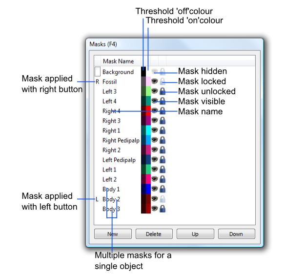
Figure 10. Masks panel.
Creating masks: The New button in the Masks panel (or the New Mask command in the Masks menu) creates a new mask. Up to 255 masks in total can be created. New masks are created with an uninformative name (e.g. Mask 2), and a random colour; it is good practice to at least rename a mask after creation.
Renaming masks: Double click on the Mask Name in the Masks panel to edit it.
Changing colours: Double click on the right-hand colour block (the Threshold ‘on’ colour) to change it. The left-hand colour block (the Threshold ‘off’ colour) is not set independently, but is a darker version of the ‘on’ colour. Double-clicking this block will bring up a dialog which enables the contrast between the light and dark versions of the colour to be set.
Selecting masks: One or more masks can be selected by left clicking on any column of the Masks panel. To select multiple masks use Ctrl-click or Shift-click. Selection is indicated by an underlined mask name. Note that mask selection and choice of left mouse button mask is not quite the same thing, though often they will coincide – it is possible for the selected mask NOT to be the left mouse button mask for instance, and more than one mask can be selected. Selection of masks is used for bulk locking or hiding, bulk deleting, mask copying, and the creation of output objects.
Mask visibility: Double-clicking a mask’s ‘eye’ icon toggles its visibility; this can be done to masks in bulk by selecting them (see below) and using the Show Selected Masks or Hide Selected Masks commands on the Masks menu.
Mask locking: Double-clicking a mask’s ‘padlock’ icon toggles its lock status; this can be done to masks in bulk by selecting them (see below) and using the Lock Selected Masks or Unlock Selected Masks commands on the Masks menu.
Re-ordering masks list: Masks can be moved up and down the list by selecting a single mask and using the Up and Down buttons on the Masks panel. This reordering only affects how the masks appear in this list; it has no effect on output or images.
Deleting masks: To delete a mask or masks first select them (see above), then click delete or use the Delete selected mask(s) command on the Masks menu. As all pixels MUST be assigned to a mask, SPIERSedit brings up a dialog to determine which mask you want to assign pixels in the to-be-deleted mask(s) to. The delete operation may take an appreciable amount of time as SPIERSedit goes through all the slices and changes all instances of the deleted mask(s) to the target mask.
4.5. Copying Masks
SPIERSedit provides four different Copy commands in the Masks menu to copy masks from or to the previous, next, current or selected slice(s); in this context current = viewed slice; next = slice after viewed slice; previous = slice before viewed slice; selected = slice(s) selected in the Slice Selector panel. These commands copy all masks selected in the Masks panel from the source to the target slice(s). Ticking the Advance one slice after copy or Go back one slice after copy options in the Masks menu combines copy operations with a single move operation. Using these options in conjunction it is possible to copy masks one slice at a time quickly through the dataset with a single command for each step. Alternatively, using the Copy… to selected commands it is possible to copy mask data from one slice to many in a single command.
4.6. Masks and Segments
If the Segment brush applies mask option on the Masks menu is ticked then drawing segments on using the brush (with either mouse button) will also apply the selected masks to the same pixels.
4.7. Masks and Curves
The Mask from curve command on the Masks menu allows the user to generate masks quickly for large numbers of slices, and is normally the most effective (though not the simplest) way to specify masks over a large number of slices. Its use is described in the section on curves.